I was working on an op amp circuit when it started to oscillate unexpectedly. I threw in more capacitance, took out capacitance, changed resistors, switched op amps, all to no avail. But then if changing your circuit doesn’t fix the problem then maybe the circuit isn’t the problem. Sure enough, it was the power supply that was oscillating. It looked just fine until you put a load on it. The other half of the dual supply failed at the same time, but it would just go dead as soon as there was a load. Maybe there was a spike on the AC line that fried them. Maybe it was the weather.
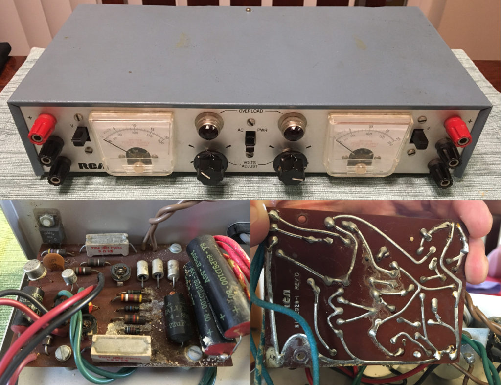
When I opened it up I was struck by how old the construction was and how crusty it had all become. The supply had been given to me by my grandfather years ago. I had assumed it was 80’s vintage but the dates on the meters were January 1972. It’s an RCA WP-702A, which appears to have continued production under the VIZ brand for many years. The design uses just 3 transistors and a few zener diodes per supply. The capacitors were clearly gone.
So it was time to learn about power supply design. I wasn’t going to throw this thing out, it’s just too handsome. So I decided to keep the transformer and front panel just as they were and design a drop-in replacement for the regulator boards, but with a slightly more modern design. I sketched out how the original circuit worked, mostly so I could get a handle on how the overload lights were switched on.
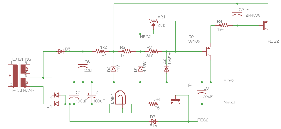
As far as I got with the existing circuit.
As you can see, turning on the overload light is pretty darn simple. They selected an incandescent bulb that begins to light at a current of 200 mA and wired it ahead of the pass transistor. All the current that comes out of the supply goes through the bulb first, and it lights itself at the maximum rated current.
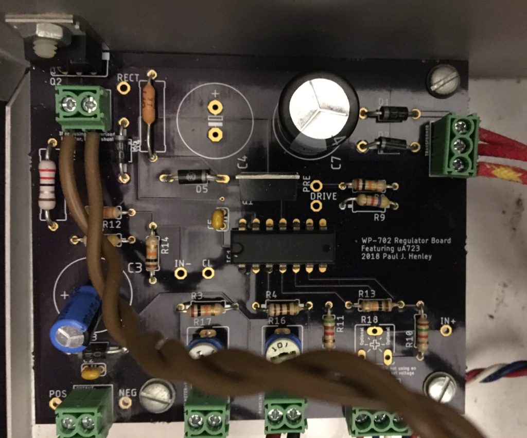
So what about the new design? I decided to upgrade to the great granddaddy of regulator IC’s: the uA723. Created in 1967 by Bob Widler, it existed when this unit was manufactured, if not when it was designed.

This design includes ideas I got from others’ schematics, but I’m not sure all of them are good. The data sheet indicates, for example, that pre-regulating the voltage to the 723 improves ripple rejection, so I made a pre-regulator from a 24 V zener (D6) I already had and used one of the power transistors (Q1) as an emitter-follower. Is this a good place to put a capacitor to make it a capacitor-multiplier as well? I would suppose so, but I’m not sure how to calculate what value should be used. It would seem to need a big one to reject 120 Hz, and it reduces the ripple pretty darn well without it.
A bigger issue, perhaps, is how to get good regulation down to 0V. There are three resistors (R12, R13, R14) in the feedback loop that try to map the nominal 0 to 20 V output range onto the 2 to 7 V input range of the error amplifier. It works well enough with a load, but the voltage creeps up when the supply is unloaded. So I put some load resistors on both the 723’s output (R9) and the output of the external pass transistor (R15). I imagine giving the chip a negative supply helps with this by keeping 0 V in its normal operating range.
One idea that was definitely good was replacing the original one-turn pots on the front panel with ten-turn pots. A 20 V range on a one-turn pot is just too much. Also, I added a fuse to the primary side of the transformer. That combined with the over-current protection of the 723 (which I set at 250 mA) makes this thing a lot safer to use.
The PCBs returned perfect and purple, but I clearly made some goofs. Some of the footprints are just too big. (I intentionally left the second filter cap unpopulated.)
All in all, I think this project turned out pretty well. The supply works, and that’s what’s most important. If it ever fails again, I’ll get to learn more about power supplies!