So we are ditching Weebly for WordPress. Neither Bluehost nor Weebly wants to support Weebly, and one of them performed an upgrade that made old content inaccessible. I’ll try to get that content back, but in the mean time I need to get some posts out.
Author: pjhenley
I Made A Thing And It Doesn’t Suck
If don’t you watch the EEVBlog, you should because Dave is the Steve Irwin of electronics. I don’t just say that because he’s Australian, but because he is knowledgable, loves what he does, and is totally Australian. One thing he recommends as a project is making a constant-current dummy load for your bench. I agree it’s a great project, not too complicated, and it produces a useful piece of equipment. The surprise when I made one, though, was that the enclosure turned out well.
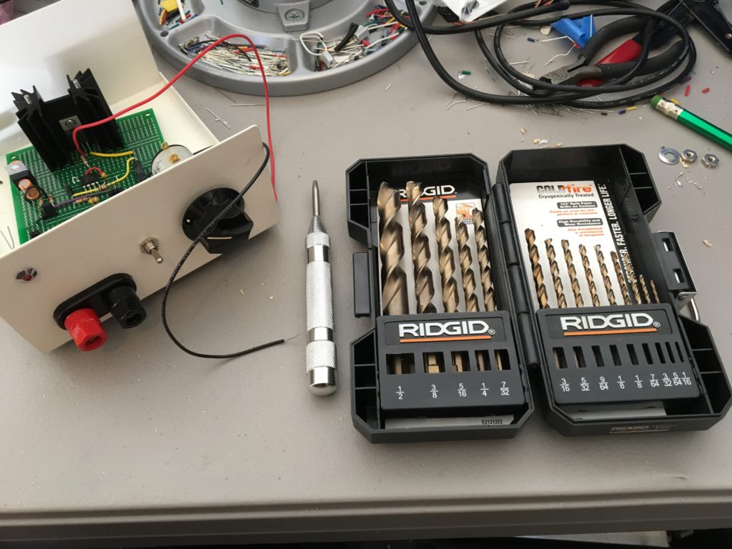
I’ve always struggled with enclosures. Trying to drill holes in those ABS project boxes from Radio Shack with a hand-held power drill is a pain. I had better luck when I had access to a drill press, but that wasn’t often. This time I went metal. The product page at Jameco says this enclosure has a steel top and aluminum body. I used a center punch and then some lightly-used RIDGID ColdFire drill bits and had no problems. The hand drill didn’t have any problem with the aluminum. I guess decent bits and the center punch are the ticket.
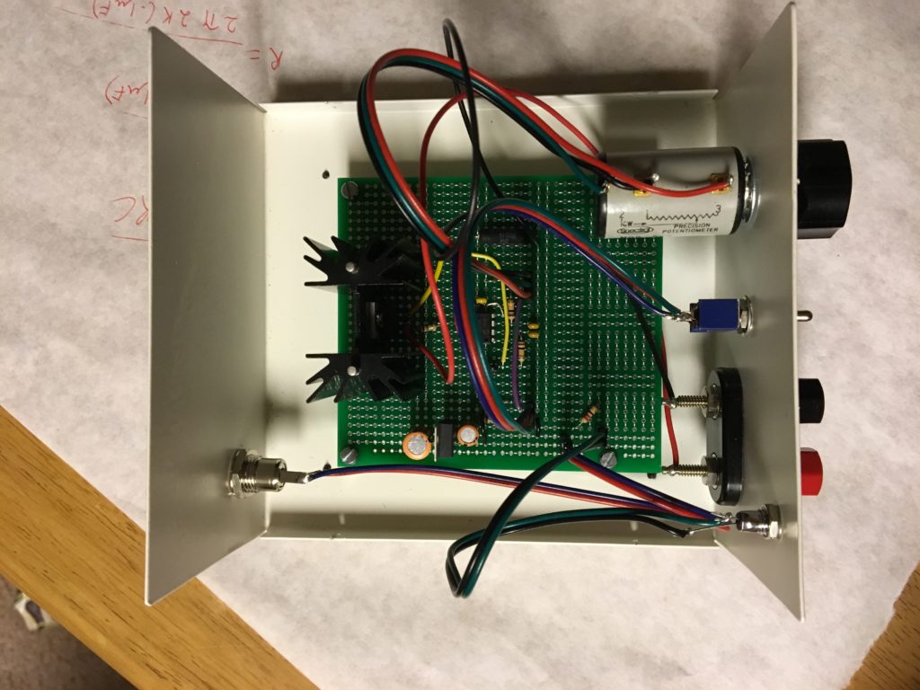
The circuit is pretty simple. An op-amp drives a power MOSFET that dissipates the power as heat. The current passes through a 2-ohm sense resistor on the way out that feeds back to the op-amp. The current level is set by a 10-turn potentiometer I picked up at a hamfest. I soldered it all up on one of those protoboards I made. There are two ranges: 25mA and 2A. You’ll notice I mounted the heat sink upside down because I didn’t want to drill holes in the protoboard. I might change that, but it works fine for now. All told, I’m pleased. I’ve already used it to characterize an old panel meter.
Most Protoboard
Most prototyping PCBs are terrible. What is it with boards like this one on the right? There are pads to solder the pins of each component to the board, but then how do you connect them? I’ve seen three options: one is to bend the leads of each component over to the component they should connect to and solder them. This ends up looking like a real old-school breadboard, like the kind that holds bread. Second, I’ve seen people drag a glob of solder across multiple pads to make a sort of trace from one pin to another. That takes a ton of solder and I can never get it to work. The third is to wrap wire around the leads of each component to make point-to-point connections. So if you want to solder everything twice, use that approach.
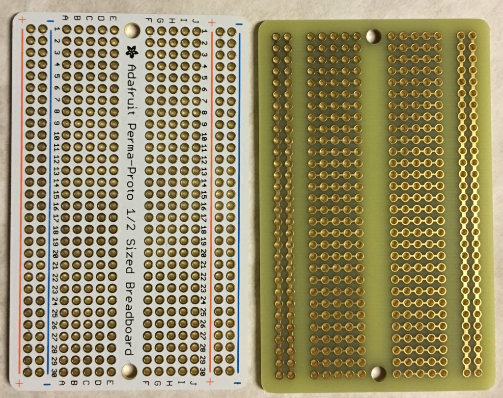
Here is a protoboard that doesn’t suck. Adafruit’s board is laid out exactly like a solderless breadboard and comes in three sizes. If you can lay your circuit out on a solderless breadboard, then you can solder it in here. The holes are plated through, so you won’t get lifted pads like you will with cheap single-sided boards. The bottom of the board (right) has no solder mask so you can cut the traces if you need to. That makes this a step up from a solderless breadboard in terms of versatility in layout.
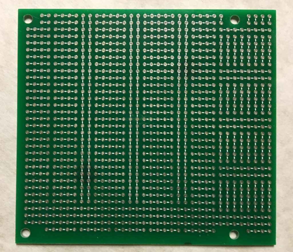
Here is my attempt at a protoboard, with several features I wanted. First, there is a place to put a two-row header at the top. Solderless breadboards don’t have a spot like that and it drives me nuts. Adafruit sells various breakout devices to accommodate the need. Second, I can lay out several chips in one row, two parallel rows, or some combination. Third, this board has mounting holes that match a commonly available enclosure I want to use! That is seriously rare for most protoboard. The two things that don’t work on this board are the area at the bottom, which was meant to accommodate tactile switches, and the holes throughout the board are too small for some components. Some diodes and resistors I want to use have fat leads and I didn’t account for that. So, on to version 2.0.
More or Less a Good Thing?
I was driving on the interstate when traffic came to a stop. I mean people got out of their cars and took a cigarette break stopped. I was headed to a funeral. There is no good news in this story.
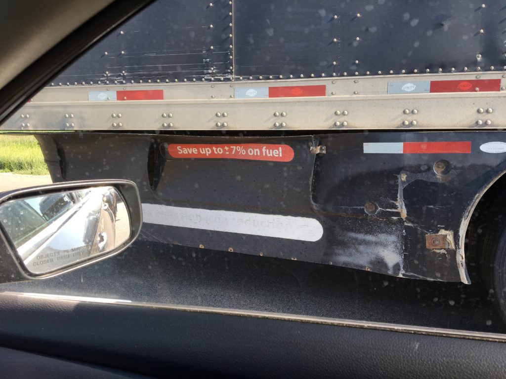
If you sit in a car for an hour, which I don’t recommend, you’ll take a closer look at things outside your car. For example, the 18-wheeler next to me was from Quebec and had a lot of the aerodynamic, fuel-saving add-ons to the trailer. In the photo above, you can see the under-trailer AirFlow Deflector or Le déflecteur AirFlow. This thing is supposed to deflect air around the wheels instead of having it drag. It will save you up to +/- 7% on fuel. Wait, what?
I can’t figure why they would put +/- except that they couldn’t figure out which was appropriate. If you say “Save -7%” is that a double-negative or emphatic negation? Is this a translation issue? In English, “Save up to 7% on fuel” is clear enough without indicating a sign. If it was possible for the addition of the deflector to add 7% to your fuel costs, this would be a very tricky way of saying so. A brochure from the company now says “up to 8.5%,” so they’ve dropped the sign in current iteration. If you can comment on what the French would be, feel free.
Elevating My Farming
Back when we owned land, we used to farm. Okay, maybe you can’t call a raised garden bed and some edible landscaping a farm, but it did produce. We’re renting again, but we want to grow a few things as a family activity. So I bought some cedar to make a elevated garden bed. I had sketched something out before going shopping, but they didn’t have the dimensions of lumber I wanted. So I did some mental calculations at the store and then kind of had to wing it. I’m pleasantly surprised that it worked.

The whole thing is made from 1×6, 1×3 and 1×2 boards. I made it 36″ long because that would use almost all of the wood. I chose the height so the preschooler can tend it easily. You can see that it is just a box, but with about 1/4″ of space between all boards to allow for drainage. To avoid screwing into any end-grain I put the 1×2 pieces in the corners to screw on the ends of the box and under the box to translate the weight of the bottom of the box onto the legs. It is lined with cloth to keep dirt from falling out. It’s pretty simple all told, I’m just amazed it looks good and went together so easily. The prize choy likes it, grown from seed.

(Word) Pressed Into Service
So I’ve ended up the administrator of a WordPress site and I’m going to have to write some custom code. This is a problem because:
- This is the first WordPress site I’ve ever touched.
- I’ve never programmed PHP.
But hey, I have enough experience with OO programing to fake it, right? Well maybe I do.
To start, let me explain that we have two plugins: WooCommerce, the most popular WordPress plugin for online commerce, and The Events Calendar, a plugin that gives you nice calendars in WordPress. The glue between the two is Event Tickets Plus, which allows you to sell tickets to your Calendar events and process them through WooCommerce to collect the money. The problem is that the integration isn’t very thorough.
Adding Event Ticket Plus Event Titles and Times to TicketS’ Associated WooCommerce Product Titles, An Exploration
When you create a type of ticket for an event, it creates an equivalent product in WooCommerce that is closely tied to the ticket. The name you give to the ticket, say, “one balcony seat”, becomes the name of a hidden product in WooCommerce. The name and price are copied over from the ticket to the product, but that’s about it. So far as Event Tickets Plus is concerned, if you want any additional data to be associated with the product then you should go find it in WooCommerce and edit it there.
This makes for some awkwardness on the WooCommerce end. For starters, when your customers look in their basket or on their receipt, all they will see is “one balcony seat” with no further details. If they put multiple tickets with the same name in their basket, then they will have no idea which is which. When you as the administrator look at the back end, all you will see is “one balcony seat” until you click through some links to find the associated event. If all your events have “one balcony seat” as a ticket option and you have, say, one thousand events, then you might have to do a lot of clicking to find the right one.
This issue is a problem for enough users that there are two code snippets in the knowledge base for Event Tickets Plus that are aimed at partially resolving it. The first is an attempt to add the event name to the product while viewing it in the shopping basket. This is a step in the right direction, but we often have repeat events so it would be nice to have the event date as well. So I started by adding that to the snippet.
add_filter( 'woocommerce_cart_item_name', 'woocommerce_cart_item_name_event_title', 10, 3 );function woocommerce_cart_item_name_event_title( $title, $values, $cart_item_key ) { $ticket_meta = get_post_meta( $values['product_id'] ); $event_id = absint( $ticket_meta['_tribe_wooticket_for_event'][0] ); if ( $event_id ) { $title = sprintf( '%s for <a href="%s" target="_blank"><strong>%s</strong></a> on %s', $title, get_permalink( $event_id ), get_the_title( $event_id ), tribe_get_start_date( $event_id ) ); } return $title;}
The other snippet that is available adds the date to the ticket information in the emailed receipt. We may have multiple events on the same day. So, I modified it to include the title of the event as well.
function tribe_add_date_to_order_title( $title, $item ) { $event = tribe_events_get_ticket_event( $item['product_id'] ); if ( $event !== false ) { $title .= ' for ' . get_the_title( $event) . ' on ' . tribe_get_start_date( $event ); } return $title;} add_filter( 'woocommerce_order_item_name', 'tribe_add_date_to_order_title', 100, 2 );
This is a good start, but it doesn’t solve my backend problem. In the admin portion of WooCommerce I still have a long list of products with identical titles. So the first thought I had was to scour the code for where the product is created from the ticket type and have it write all of the information right into the product title. That would eliminate the need for the above two snippets.
To do this, I have to find if and where the authors of Event Tickets Plus put a hook to which I can attach my code. In the snippets above, you can see that the new functions are attached to the code using the “add_filter” function and a string associated with the base code. Those strings, ‘woocommerce_cart_item_name’ and ‘woocommerce_order_item_name’ were written into the base code by the authors of WooCommerce so others could modify the behavior of WooCommerce without editing the code itself. This reduces the chance that an update to WooCommerce will overwrite the changes or break them. I have to say that both WordPress and the writers of its plugins have done a great job of making their code extensible. Hooks for additional code are just about everywhere.
So I don’t have to search too long before I find the appropriate tag at the end of the ticket-creation code. I add a little bit of code to change the name of the WooCommerce product that is created to back the ticket so that it includes the name of the event as well as the ticket type and… unexpected behavior ensues. In particular, changing the WooCommerce product’s name changes the Event Tickets Plus ticket name to match. Either there is code elsewhere that keeps the two in sync or, quite possibly, the ticket and the event are the same object (that is, the same ‘post’ in the database) and there is no way to disentangle them enough to have different names.
Since the name collision problem only annoys the administrator of the site, and not the end user, I think this is all the effort I’m going to put into this. If you happen to know how any of this works, by all means comment so, but I may not put much more effort into this unless someone starts paying me. 😉
Winning
Remember that multimeter I was so excited about a few months ago? It’s the one that uses your smartphone as the display. Well, I used its best two features within a week. First, my car was having trouble starting. We had a cold snap, so it was a good bet the battery had died. However, no one wanted to come into the garage with me to crank the engine while I watched the battery voltage on the multimeter. You know, something about it being below zero and not wanting to put boots on.
Well that’s NO PROBLEM because I hooked up the meter to the battery and watched my smart phone as I got in the car myself and cranked the engine. Or didn’t, because the battery voltage dropped to 7V as soon as I opened the door. When the headlights are on “auto” and you open the door, the computer checks to see how dark it is and then turns them on if needed. That was enough to show the battery was dead.
But wait, there’s more! I later needed to see if using batteries to power a desktop gadget I was building was viable. I thought the batteries would be dead in about a day and a half. So I slipped an SD card into the meter and had it log the current through the device as I went to bed. The meter has no problem itself with batteries. It’ll sit there logging for months on 2 AA’s. The gadget design will have to wait for another post.
Someone Is Wrong on The Internet
I know, I know, there are plenty of people on the internet who are wrong about a good number of things, but good gravy this irks me. Check out what I found on a do-it-yourself reference site.

Did you catch it? Okay, maybe you didn’t, and that’s okay, but by the end of this post you might be as annoyed as I am because that is not a f#$%ing Phillips head driver. That is a Pozidriv driver. They’re different. Now I know that when it comes to putting art into an article, it’s often left to editors and not the writers. It’s not always the case that the editor has mastered the content that the writer has. That doesn’t seem to be what happened here, though. Check out the text.

There it is: the error extends to the text. The writer claims a Phillips head “does not taper.” The drive in the image doesn’t taper, but the drive in the image is not a Phillips. In fact it is the taper or lack thereof that differentiates the Phillips and Pozidriv. Here is a comparison of a Phillips next to a #2 Pozidriv, courtesy of my toolbox.

As you can see, the blades on the Phillips (top) are tapered, while the blades on the Pozidriv are not. Plus, there are those extra splines between the blades of the Pozidriv that are a dead giveaway that it’s different. If you’ve ever had to lean on a Phillips to get it to stop popping out of a tight screw, then you have experienced the difference. The Phillips drive is designed “cam out” of the recess when the screw is too tight. This is to avoid applying too much force to the screw and twisting the head off of it. Pozidriv screws are designed to withstand more torque, and so they have a driver capable of delivering more torque without popping out of the screw head.
So how did the author get it so wrong? Given that that the article reads like a freshman essay that’s been padded out for length, I’d say this article exists just to produce ad revenue. I imagine the work put into it was 99% search engine optimization and 1% content generation, with no time to check Wikipedia.
Is That DC-DC Converter Worth It?

So I have a project where everything runs at 12V except the brains of the operation, a Raspberry Pi, which needs 5V. This is a situation where I knew I didn’t want to reach for a 7805 linear regulator. Sure, I used one for prototyping because I didn’t want to wait for parts to arrive, but a linear regulator is really inefficient and the project I’m building is to run 24/7. So I set out to find a cheap DC-DC converter and settled on the VXO7805-1000, which is meant to be a drop-in replacement for the LM7805 pictured on the left. Of course, as soon as it arrived I wanted to know just how much more efficient it was, and how long it would take to make up the difference in price, so I set up a test.

I started the test with the same regulated 12V supply I expected to use in the final product, plugged into my homebrew inline current and voltage monitor. From there the power went to the protoboard where I set up each regulator with a 10uF capacitor on the input side and a 22uF capacitor on the output side. Those values were recommended by the manufacturer of the DC-DC converter. From there the power goes through an ammeter and then to (swoon) one of those giant rheostats I’m always so excited about. Let’s talk about it.

This is by far the coolest of the Ohmite rheostats I’ve picked up at hamfests. You can see that the tap in this picture is resting in a spot where there are no windings. That’s how they designed this rheostat to have a “switch off” position. There’s a bump so you can feel it “click on” when it reaches the windings. Then you can see they used three different gauges of wire in the windings. This is how they made it roughly logarithmic. The whole thing is 75 ohms and perfect for an adjustable DC dummy load application like this.
The procedure for the test was to run each regulator at a number of output currents and measure the input currents. An additional meter helped measure the output voltage so we could calculate the power output. Subtracting from the input power, we found the power lost inside the regulator. Working from the cost of electricity in our area and the cost of each regulator, I could then find the break-even point for the more efficient DC-DC regulator.
The data for the 1000mA test should have an asterisk. Somewhere around 700mA the heat in the linear regulator becomes too much and it shuts down. I added a heat sink so I could continue the test, but that changes the cost of the linear regulator significantly, making the DC-DC regulator an even better deal. My application will draw about 250mA. It should take less than 1.5 years to have the energy savings of the DC-DC regulator more than pay for its higher cost. Not bad! I wonder, though, if I should be comparing the regulators at the same power output rather than current output. The output voltages are similar, so this analysis should be good as a ball-park estimate regardless.
Junk Box Hero

So, I helped a fellow ham out by buying this from him. He sold some of his real estate and just can’t keep all the junk he used to. He’s been unloading it at hamfests all summer. What is it? It’s five identical 5k rheostats wired into a terminal block. But look at the workmanship!

The first thing I’ll point out is the rack mount. This is basically a bunch of stock metal bars bent, drilled and tapped. Some of this is off-the-shelf, like the terminal block, but I suspect the rest is custom-fabricated. We know the unit all together is a one-off. I feel like the metal to make this would cost much more these days because they just don’t make things this thick anymore. I don’t mean that they don’t produce metal bars this thick, just that they don’t get used much. Everything now is thin and light. This is built like a WWII battleship.
The next thing I’d like to point out is the wiring. That is cotton-insulated wire, making this a pretty old piece of equipment. The seller tells me that the man who built this insisted on wiring it up to AT&T’s standards, which requires tying off the wires every half-inch. I haven’t found a reference to this standard, but if you have one let me know from the contact page. Cotton-insulated wire is making a comeback amongst audiophiles who believe it gives a more natural sound than plastic insulated wire. Unfortunately, my ethernet wires are plastic-insulated. Audiophiles won’t be able to hear how naturally I’m rolling my eyes right now.

So what was this used for? The seller told me, but I didn’t quite follow. Tuning some sort of loops, based on the labeling. I assume the labeling is newer than the unit, since it is made of that adhesive labeling tape. Maybe not, though, I’m not sure how old those labelers are. The rheostats are made by ohmite, like the other ones I own. He also sold me a 10-turn potentiometer with matching dial, which is what I wanted. I may keep the rheostats but recycle the metal. It’s memorialized here well enough.