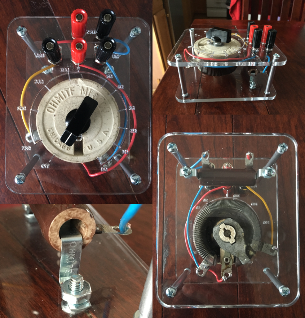
For a recent power supply project (more on that later) I needed a dummy load for testing. So I reached for my favorite Ohmite rheostat: 75 ohms with an approximate log taper and an off position. This is one I picked up at a hamfest real cheap. To test at the max voltage and current, I needed 100 ohms, however, so I added in a 25 ohm fixed wire-wound resistor for those tests. They worked really well, except they were just loose on the bench connected with gator clips that would sometimes slip off. So I built an enclosure for them.

The enclosure isn’t fully enclosed, as you can see. It consists of just two laser-cut pieces of acrylic with four 3″ 8-32 standoffs. The open sides allow the resistors some ventilation. It doesn’t have feet yet, but I plan to add non-marking rubber feet held on by the lower screws. I was pleased to find some short scraps of brightly colored solid wire in my junk bin.
I decided to add a scale for the rheostat. I did this by sketching up most of the layout in GeoGebra and then printing it out on paper. I poked the shaft of the rheostat through the paper, added a knob, and then used an ohm meter to find the correct angles. If I was laser-cutting it over, though, I would make the numbers bigger and not so deep. They’re readable, but could be clearer.
I like the layout of the connectors. To add the 25 ohm fixed resistor to the rheostat you can just short the black terminals at the right and then use the red terminals for a 100 ohm to 25 ohm range. The black terminal at left will rarely be used, but is available if I need to use the rheostat as a voltage divider.
A word about GeoGebra: I was at least 40 times faster sketching this up with GeoGebra than I would have been with the more commonly used Inkscape. The fact is, Inkscape isn’t made for technical drawings. Getting precision out of it takes work, including a lot of calculation on the part of the user. GeoGebra makes it trivial to put every circle, arc, and segment exactly where you want it with infinite precision.